Skip to content
Products
Products
Systems
Cables
Modules
Cabinets
Controllers
Power
Parts
Merchandise
Articles
Articles
Stories
Discover 5U
Learn
Support
Support
Videos
Spec Sheets
Frequently Asked Questions
support@synthesizers.com
About
About
History
Manufacturing
Contact Us
Community
Community
Artists
Photo Galleries
YouTube
Facebook
Instagram
Archives
Log in
Country/region
Afghanistan (AFN ؋)
Åland Islands (EUR €)
Albania (ALL L)
Algeria (DZD د.ج)
Andorra (EUR €)
Angola (USD $)
Anguilla (XCD $)
Antigua & Barbuda (XCD $)
Argentina (USD $)
Armenia (AMD դր.)
Aruba (AWG ƒ)
Ascension Island (SHP £)
Australia (AUD $)
Austria (EUR €)
Azerbaijan (AZN ₼)
Bahamas (BSD $)
Bahrain (USD $)
Bangladesh (BDT ৳)
Barbados (BBD $)
Belarus (USD $)
Belgium (EUR €)
Belize (BZD $)
Benin (XOF Fr)
Bermuda (USD $)
Bhutan (USD $)
Bolivia (BOB Bs.)
Bosnia & Herzegovina (BAM КМ)
Botswana (BWP P)
Brazil (USD $)
British Indian Ocean Territory (USD $)
British Virgin Islands (USD $)
Brunei (BND $)
Bulgaria (BGN лв.)
Burkina Faso (XOF Fr)
Burundi (BIF Fr)
Cambodia (KHR ៛)
Cameroon (XAF Fr)
Canada (CAD $)
Cape Verde (CVE $)
Caribbean Netherlands (USD $)
Cayman Islands (KYD $)
Central African Republic (XAF Fr)
Chad (XAF Fr)
Chile (USD $)
China (CNY ¥)
Christmas Island (AUD $)
Cocos (Keeling) Islands (AUD $)
Colombia (USD $)
Comoros (KMF Fr)
Congo - Brazzaville (XAF Fr)
Congo - Kinshasa (CDF Fr)
Cook Islands (NZD $)
Costa Rica (CRC ₡)
Côte d’Ivoire (XOF Fr)
Croatia (EUR €)
Curaçao (ANG ƒ)
Cyprus (EUR €)
Czechia (CZK Kč)
Denmark (DKK kr.)
Djibouti (DJF Fdj)
Dominica (XCD $)
Dominican Republic (DOP $)
Ecuador (USD $)
Egypt (EGP ج.م)
El Salvador (USD $)
Equatorial Guinea (XAF Fr)
Eritrea (USD $)
Estonia (EUR €)
Eswatini (USD $)
Ethiopia (ETB Br)
Falkland Islands (FKP £)
Faroe Islands (DKK kr.)
Fiji (FJD $)
Finland (EUR €)
France (EUR €)
French Guiana (EUR €)
French Polynesia (XPF Fr)
French Southern Territories (EUR €)
Gabon (XOF Fr)
Gambia (GMD D)
Georgia (USD $)
Germany (EUR €)
Ghana (USD $)
Gibraltar (GBP £)
Greece (EUR €)
Greenland (DKK kr.)
Grenada (XCD $)
Guadeloupe (EUR €)
Guatemala (GTQ Q)
Guernsey (GBP £)
Guinea (GNF Fr)
Guinea-Bissau (XOF Fr)
Guyana (GYD $)
Haiti (USD $)
Honduras (HNL L)
Hong Kong SAR (HKD $)
Hungary (HUF Ft)
Iceland (ISK kr)
India (INR ₹)
Indonesia (IDR Rp)
Iraq (USD $)
Ireland (EUR €)
Isle of Man (GBP £)
Israel (ILS ₪)
Italy (EUR €)
Jamaica (JMD $)
Japan (JPY ¥)
Jersey (USD $)
Jordan (USD $)
Kazakhstan (KZT 〒)
Kenya (KES KSh)
Kiribati (USD $)
Kosovo (EUR €)
Kuwait (USD $)
Kyrgyzstan (KGS som)
Laos (LAK ₭)
Latvia (EUR €)
Lebanon (LBP ل.ل)
Lesotho (USD $)
Liberia (USD $)
Libya (USD $)
Liechtenstein (CHF CHF)
Lithuania (EUR €)
Luxembourg (EUR €)
Macao SAR (MOP P)
Madagascar (USD $)
Malawi (MWK MK)
Malaysia (MYR RM)
Maldives (MVR MVR)
Mali (XOF Fr)
Malta (EUR €)
Martinique (EUR €)
Mauritania (USD $)
Mauritius (MUR ₨)
Mayotte (EUR €)
Mexico (USD $)
Moldova (MDL L)
Monaco (EUR €)
Mongolia (MNT ₮)
Montenegro (EUR €)
Montserrat (XCD $)
Morocco (MAD د.م.)
Mozambique (USD $)
Myanmar (Burma) (MMK K)
Namibia (USD $)
Nauru (AUD $)
Nepal (NPR ₨)
Netherlands (EUR €)
New Caledonia (XPF Fr)
New Zealand (NZD $)
Nicaragua (NIO C$)
Niger (XOF Fr)
Nigeria (NGN ₦)
Niue (NZD $)
Norfolk Island (AUD $)
North Macedonia (MKD ден)
Norway (USD $)
Oman (USD $)
Pakistan (PKR ₨)
Palestinian Territories (ILS ₪)
Panama (USD $)
Papua New Guinea (PGK K)
Paraguay (PYG ₲)
Peru (PEN S/.)
Philippines (PHP ₱)
Pitcairn Islands (NZD $)
Poland (PLN zł)
Portugal (EUR €)
Qatar (QAR ر.ق)
Réunion (EUR €)
Romania (RON Lei)
Russia (USD $)
Rwanda (RWF FRw)
Samoa (WST T)
San Marino (EUR €)
São Tomé & Príncipe (STD Db)
Saudi Arabia (SAR ر.س)
Senegal (XOF Fr)
Serbia (RSD РСД)
Seychelles (USD $)
Sierra Leone (SLL Le)
Singapore (SGD $)
Sint Maarten (ANG ƒ)
Slovakia (EUR €)
Slovenia (EUR €)
Solomon Islands (SBD $)
Somalia (USD $)
South Africa (USD $)
South Georgia & South Sandwich Islands (GBP £)
South Korea (KRW ₩)
South Sudan (USD $)
Spain (EUR €)
Sri Lanka (LKR ₨)
St. Barthélemy (EUR €)
St. Helena (SHP £)
St. Kitts & Nevis (XCD $)
St. Lucia (XCD $)
St. Martin (EUR €)
St. Pierre & Miquelon (EUR €)
St. Vincent & Grenadines (XCD $)
Sudan (USD $)
Suriname (USD $)
Svalbard & Jan Mayen (USD $)
Sweden (SEK kr)
Switzerland (CHF CHF)
Taiwan (TWD $)
Tajikistan (TJS ЅМ)
Tanzania (TZS Sh)
Thailand (THB ฿)
Timor-Leste (USD $)
Togo (XOF Fr)
Tokelau (NZD $)
Tonga (TOP T$)
Trinidad & Tobago (TTD $)
Tristan da Cunha (GBP £)
Tunisia (USD $)
Türkiye (USD $)
Turkmenistan (USD $)
Turks & Caicos Islands (USD $)
Tuvalu (AUD $)
U.S. Outlying Islands (USD $)
Uganda (UGX USh)
Ukraine (UAH ₴)
United Arab Emirates (AED د.إ)
United Kingdom (GBP £)
United States (USD $)
Uruguay (UYU $)
Uzbekistan (UZS )
Vanuatu (VUV Vt)
Vatican City (EUR €)
Venezuela (USD $)
Vietnam (VND ₫)
Wallis & Futuna (XPF Fr)
Western Sahara (MAD د.م.)
Yemen (YER ﷼)
Zambia (USD $)
Zimbabwe (USD $)
Update country/region
Country/region
USD $ | United States
AFN ؋ |
Afghanistan
EUR € |
Åland Islands
ALL L |
Albania
DZD د.ج |
Algeria
EUR € |
Andorra
USD $ |
Angola
XCD $ |
Anguilla
XCD $ |
Antigua & Barbuda
USD $ |
Argentina
AMD դր. |
Armenia
AWG ƒ |
Aruba
SHP £ |
Ascension Island
AUD $ |
Australia
EUR € |
Austria
AZN ₼ |
Azerbaijan
BSD $ |
Bahamas
USD $ |
Bahrain
BDT ৳ |
Bangladesh
BBD $ |
Barbados
USD $ |
Belarus
EUR € |
Belgium
BZD $ |
Belize
XOF Fr |
Benin
USD $ |
Bermuda
USD $ |
Bhutan
BOB Bs. |
Bolivia
BAM КМ |
Bosnia & Herzegovina
BWP P |
Botswana
USD $ |
Brazil
USD $ |
British Indian Ocean Territory
USD $ |
British Virgin Islands
BND $ |
Brunei
BGN лв. |
Bulgaria
XOF Fr |
Burkina Faso
BIF Fr |
Burundi
KHR ៛ |
Cambodia
XAF Fr |
Cameroon
CAD $ |
Canada
CVE $ |
Cape Verde
USD $ |
Caribbean Netherlands
KYD $ |
Cayman Islands
XAF Fr |
Central African Republic
XAF Fr |
Chad
USD $ |
Chile
CNY ¥ |
China
AUD $ |
Christmas Island
AUD $ |
Cocos (Keeling) Islands
USD $ |
Colombia
KMF Fr |
Comoros
XAF Fr |
Congo - Brazzaville
CDF Fr |
Congo - Kinshasa
NZD $ |
Cook Islands
CRC ₡ |
Costa Rica
XOF Fr |
Côte d’Ivoire
EUR € |
Croatia
ANG ƒ |
Curaçao
EUR € |
Cyprus
CZK Kč |
Czechia
DKK kr. |
Denmark
DJF Fdj |
Djibouti
XCD $ |
Dominica
DOP $ |
Dominican Republic
USD $ |
Ecuador
EGP ج.م |
Egypt
USD $ |
El Salvador
XAF Fr |
Equatorial Guinea
USD $ |
Eritrea
EUR € |
Estonia
USD $ |
Eswatini
ETB Br |
Ethiopia
FKP £ |
Falkland Islands
DKK kr. |
Faroe Islands
FJD $ |
Fiji
EUR € |
Finland
EUR € |
France
EUR € |
French Guiana
XPF Fr |
French Polynesia
EUR € |
French Southern Territories
XOF Fr |
Gabon
GMD D |
Gambia
USD $ |
Georgia
EUR € |
Germany
USD $ |
Ghana
GBP £ |
Gibraltar
EUR € |
Greece
DKK kr. |
Greenland
XCD $ |
Grenada
EUR € |
Guadeloupe
GTQ Q |
Guatemala
GBP £ |
Guernsey
GNF Fr |
Guinea
XOF Fr |
Guinea-Bissau
GYD $ |
Guyana
USD $ |
Haiti
HNL L |
Honduras
HKD $ |
Hong Kong SAR
HUF Ft |
Hungary
ISK kr |
Iceland
INR ₹ |
India
IDR Rp |
Indonesia
USD $ |
Iraq
EUR € |
Ireland
GBP £ |
Isle of Man
ILS ₪ |
Israel
EUR € |
Italy
JMD $ |
Jamaica
JPY ¥ |
Japan
USD $ |
Jersey
USD $ |
Jordan
KZT 〒 |
Kazakhstan
KES KSh |
Kenya
USD $ |
Kiribati
EUR € |
Kosovo
USD $ |
Kuwait
KGS som |
Kyrgyzstan
LAK ₭ |
Laos
EUR € |
Latvia
LBP ل.ل |
Lebanon
USD $ |
Lesotho
USD $ |
Liberia
USD $ |
Libya
CHF CHF |
Liechtenstein
EUR € |
Lithuania
EUR € |
Luxembourg
MOP P |
Macao SAR
USD $ |
Madagascar
MWK MK |
Malawi
MYR RM |
Malaysia
MVR MVR |
Maldives
XOF Fr |
Mali
EUR € |
Malta
EUR € |
Martinique
USD $ |
Mauritania
MUR ₨ |
Mauritius
EUR € |
Mayotte
USD $ |
Mexico
MDL L |
Moldova
EUR € |
Monaco
MNT ₮ |
Mongolia
EUR € |
Montenegro
XCD $ |
Montserrat
MAD د.م. |
Morocco
USD $ |
Mozambique
MMK K |
Myanmar (Burma)
USD $ |
Namibia
AUD $ |
Nauru
NPR ₨ |
Nepal
EUR € |
Netherlands
XPF Fr |
New Caledonia
NZD $ |
New Zealand
NIO C$ |
Nicaragua
XOF Fr |
Niger
NGN ₦ |
Nigeria
NZD $ |
Niue
AUD $ |
Norfolk Island
MKD ден |
North Macedonia
USD $ |
Norway
USD $ |
Oman
PKR ₨ |
Pakistan
ILS ₪ |
Palestinian Territories
USD $ |
Panama
PGK K |
Papua New Guinea
PYG ₲ |
Paraguay
PEN S/. |
Peru
PHP ₱ |
Philippines
NZD $ |
Pitcairn Islands
PLN zł |
Poland
EUR € |
Portugal
QAR ر.ق |
Qatar
EUR € |
Réunion
RON Lei |
Romania
USD $ |
Russia
RWF FRw |
Rwanda
WST T |
Samoa
EUR € |
San Marino
STD Db |
São Tomé & Príncipe
SAR ر.س |
Saudi Arabia
XOF Fr |
Senegal
RSD РСД |
Serbia
USD $ |
Seychelles
SLL Le |
Sierra Leone
SGD $ |
Singapore
ANG ƒ |
Sint Maarten
EUR € |
Slovakia
EUR € |
Slovenia
SBD $ |
Solomon Islands
USD $ |
Somalia
USD $ |
South Africa
GBP £ |
South Georgia & South Sandwich Islands
KRW ₩ |
South Korea
USD $ |
South Sudan
EUR € |
Spain
LKR ₨ |
Sri Lanka
EUR € |
St. Barthélemy
SHP £ |
St. Helena
XCD $ |
St. Kitts & Nevis
XCD $ |
St. Lucia
EUR € |
St. Martin
EUR € |
St. Pierre & Miquelon
XCD $ |
St. Vincent & Grenadines
USD $ |
Sudan
USD $ |
Suriname
USD $ |
Svalbard & Jan Mayen
SEK kr |
Sweden
CHF CHF |
Switzerland
TWD $ |
Taiwan
TJS ЅМ |
Tajikistan
TZS Sh |
Tanzania
THB ฿ |
Thailand
USD $ |
Timor-Leste
XOF Fr |
Togo
NZD $ |
Tokelau
TOP T$ |
Tonga
TTD $ |
Trinidad & Tobago
GBP £ |
Tristan da Cunha
USD $ |
Tunisia
USD $ |
Türkiye
USD $ |
Turkmenistan
USD $ |
Turks & Caicos Islands
AUD $ |
Tuvalu
USD $ |
U.S. Outlying Islands
UGX USh |
Uganda
UAH ₴ |
Ukraine
AED د.إ |
United Arab Emirates
GBP £ |
United Kingdom
USD $ |
United States
UYU $ |
Uruguay
UZS |
Uzbekistan
VUV Vt |
Vanuatu
EUR € |
Vatican City
USD $ |
Venezuela
VND ₫ |
Vietnam
XPF Fr |
Wallis & Futuna
MAD د.م. |
Western Sahara
YER ﷼ |
Yemen
USD $ |
Zambia
USD $ |
Zimbabwe
Facebook
Instagram
TikTok
YouTube
Products
Systems
Cables
Modules
Cabinets
Controllers
Power
Parts
Merchandise
Articles
Stories
Discover 5U
Learn
Support
Videos
Spec Sheets
Frequently Asked Questions
support@synthesizers.com
About
History
Manufacturing
Contact Us
Community
Artists
Photo Galleries
YouTube
Facebook
Instagram
Archives
Search
Log in
Cart
Skip to product information
Open media 1 in modal
Open media 2 in modal
Q108 Amplifier opens full screen video in same window.
Open media 3 in modal
Play video
Q108 Amplifier opens full screen video in same window.
Open media 4 in modal
Play video
Q108 Amplifier opens full screen video in same window.
Open media 5 in modal
Play video
1
/
of
5
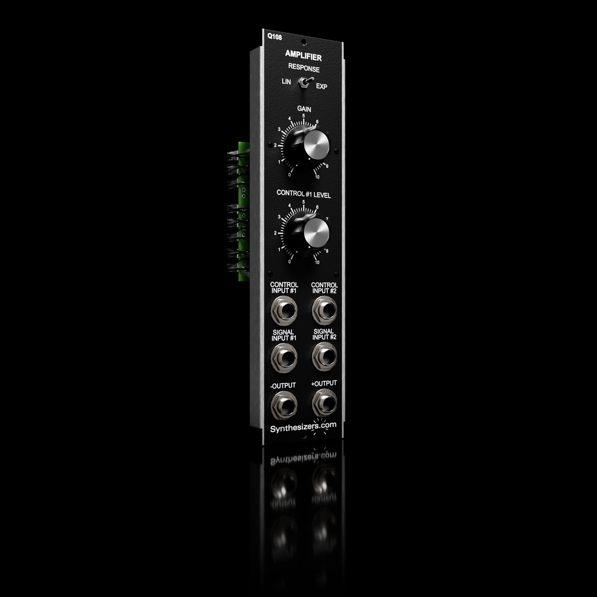
Q108 Amplifier
Q108 Amplifier
Regular price
$150.00
Regular price
Sale price
$150.00
Unit price
/
per
Sale
Sold out
Shipping
calculated at checkout.
Product variants
Default Title - $150.00
Quantity
(
0
in cart)
Decrease quantity for Q108 Amplifier
Increase quantity for Q108 Amplifier
Add to cart
I have a Question about this product
Couldn't load pickup availability
Refresh
Translation missing: en.general.accessibility.sidebar
View full details
Choosing a selection results in a full page refresh.
Opens in a new window.